
Click to enlarge
Out of stock
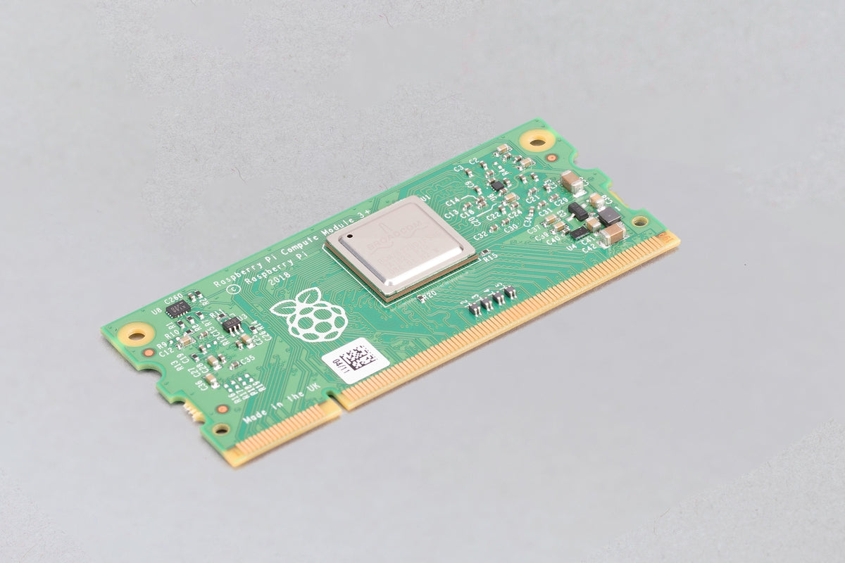
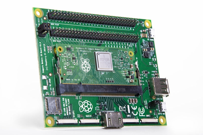
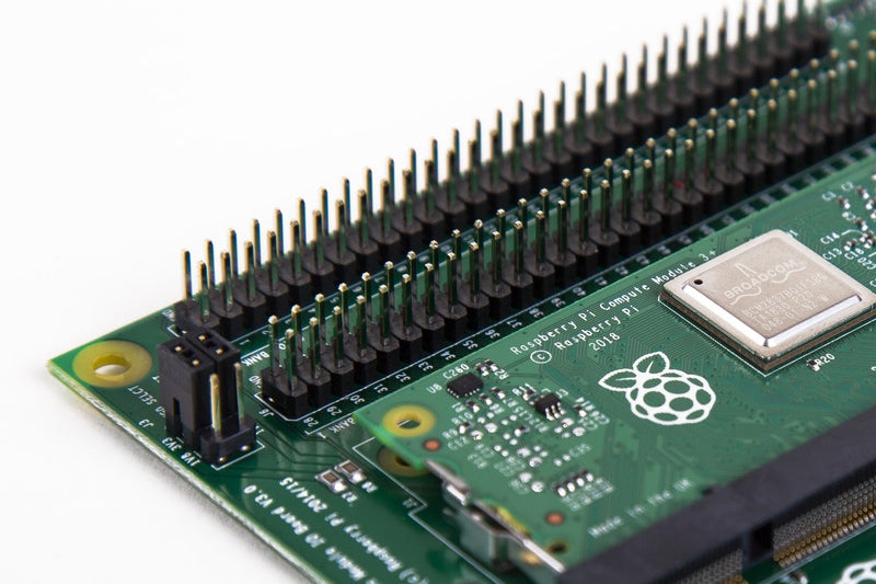
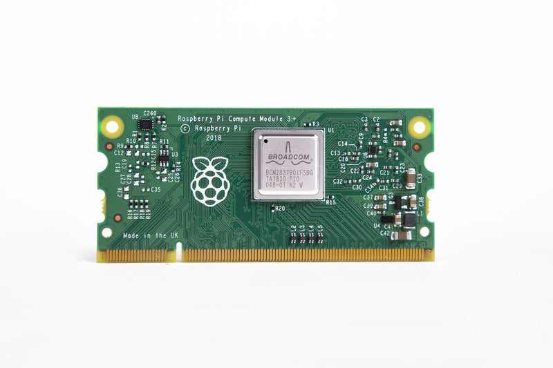
Compute Module 3+ Development Kit
SKU: SE-RPI-64
Rs. 8,000.00
Order in The Next to get it by
Real Time 81 Visitor Right Now
Description
Specification
Datasheet
Certification
Description
Specification
Datasheet
Certification
The Compute Module Development Kit has undergone extensive compliance testing, and meets the following European standards:
- Electromagnetic Compatibility Directive (EMC) 2014/30/EU
- Restriction of Hazardous Substances (RoHS) Directive 2011/65/EU
View and download global compliance certificates for Raspberry Pi products.
The Adopted Trademarks HDMI, HDMI High-Definition Multimedia Interface, and the HDMI Logo are trademarks or registered trademarks of HDMI Licensing Administrator, Inc. in the United States and other countries.
